This page consists of an explanation of Voltage-drive and Current-drive, which enables us understand why Solid-state and Valve amps sound different. When solid-state amps were introduced there was little interest taken in how amplifiers and speakers interact. Manufacturers of amplifiers and speakers have little in common. It serves the interest of marketing to separate speaker systems and amplifiers into different categories and brand names enabling retailers to have greater control in how customers are influenced and profits made. This imposed marketing separation also suits those who attain notoriety as Thiel Small loudspeaker design experts. Academic mis-application of Thiel Small parameters has resulted in a bewildering convolution of speakers designs many of which perform pooly. This is also the reason for the traditional marketing hostility against integrated active sound systems, but this is starting to change.
The complimentary page (Valve / Solid-state) in the Valve amps chapter, approaches the difference between these amps from the perspective of the physics of a valve amp, whereas this page describes the difference from a technical perspective of a solid-state amp.
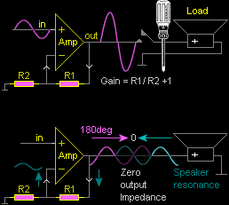
Comparator The first stage of the amplifier is called a comparator, and has 2 inputs. The +non-inverting input is connected to the incoming signal. The -inverting input is connected to the output of the amplifier through R1 (negative feedback). The comparator compares the 2 inputs, and forces the amplifier output to match the incoming signal, except for increased size. The way the comparator is set up defines the operation of the amplifier as voltage-drive or current-drive.

Voltage drive is the established conventional method of connecting R1 directly to the output of the amplifier. The gain of the amplifier is controlled independently by the ratio of R1 and R2. Anything (including speakers) connected to the output of an amplifier has no effect on amplifier gain. It makes no difference to the gain of the amplifier if there is a load, or no load, or what the load is. The output voltage will be the result of the ratio of R1 and R2. If a screwdriver is placed across the output, the amplifier will attempt to provide the correct output voltage as a function of R1 and R2. If the short circuit protection in the amplifier does not activate quickly the amplifier will self destruct.
Zero output Impedance A voltage drive amp gives the appearance to the speaker (load) that it has a short circuit is across it. Any electrical signal AC or DC that is externally applied to the output of an the amplifier is fed back through R1 to the -inverting input, which is amplified in the reverse direction (180deg) and immediately cancels out (shorts out) the signal form the external source. The voice coil of speaker also generates electricity as it moves in and out. The voice coil generates maximum electricity at the speakers Resonance frequency, described as Back EMF (electro motive force). Any electrical signal from the speaker is fed back through R1 to the -inverting input, which is amplified in the reverse direction (180deg) and immediately shorts out (damps) the resonance of the speaker. Zero output Impedance is also described as 100% Damping factor.
Speaker Impedance Ω Impedance is resistance R that varies with frequency and this includes all cone speakers. Speaker Impedance is traditionally symbolised with the Greek letter Omega Ω to represent its Resistance R. Speaker Impedance can be written as 8Ω or 8R. The DC resistance of the voice coil in most 8Ω speakers is approx 6R. Most cone speakers are 8R between 400Hz to 600Hz only.

At fundamental resonance (Fs) the speaker Impedance will rise steeply to 30R - 40R as in the above pic. Above 600Hz the Impedance of a voice coil in most cone speakers will begin to rise due to its inductive reactance and may reach 20R to 60R at 10kHz. The Impedance of a speaker varies by magnitudes 500% approx across the frequency range. Some cone speakers have an internal magnetic shorting ring which attempts to minimise Impedance variation, but at the cost of reducing efficiency.

Power into the speaker is dependant on its Impedance at any particular frequency. As the speaker Impedance increases, power to the speaker decreases. In the above pic the speaker Impedance at Resonance is 32R therefore power decreases to 25%. Only between 200Hz to 600Hz is the speaker 8R. At 10kHz the speaker Impedance is 32R and the power decreases to 25%. Across the frequency spectrum the average impedance of a speaker is above 8R. Due to the changing Impedance of the voice coil, a cone speaker receives maximum power at mid frequencies but minimum power at bass and high frequencies.
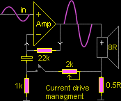
Current drive and Constant current. is technical term to describe the inverse of Voltage drive. The ratio of R1 and R2 controls the gain of the amplifier Gain = R1 / R2 +1 as previously described. R1 and R2 are in series to ground and also act as a load to the amplifier. In current drive R1 is the 8Ω speaker R2 = 0.5R the gain of the amplifier is 17 (8Ω / 0.5R +1 = 17). However the speaker Impedance varies with frequency, and as the Impedance of the speaker increases so does the gain of the amplifier. At Resonance the speaker is 32R gain and power is increased x 4. Between 200Hz and 600Hz the speaker Impedance will be 8R gain will be normal. At 10kHz the Impedance of the speaker is 32R gain and power will be increased x 4. Also any electrical signal AC or DC that is externally applied to the output of an the amplifier from the speaker (load) as back EMF is not fed back through R1 to the amplifiers -inverting input. Therefore the output Impedance of the amplifier is Infinite, Damping factor is zero.

Current drive comparison If the speaker Impedance remained a constant 8R over the frequency spectrum there would be little to zero auditory difference between Voltage-drive and Current-drive. All cone speakers vary Impedance over the frequency spectrum (approx 500%) and the auditory difference between Voltage-drive and Current-drive is very noticeable to extreme. With most cone speakers, Voltage-drive appears to sound flat and dead, the bass and high frequencies appear reduced, as if a blanket has been placed over the speaker.

- Voltage-drive power is inversely proportional to speaker Ω
therefore power decreases as the speaker Impedance rises. - Current-drive power is directly proportional to speaker Impedance
therefore power increases as the speaker Impedance rises.
In Current-drive the bass and hi-frequencies appear to spring to life with clarity and detail. If given the opportunity for comparison, every human with ears regardless of age, sex, creed or color will hear the difference and will immediately choose Current-drive as the preferred listening option, if the option was available. Every musician (guitar and bass player) instantly hears the brighter response of Current-drive and will immediately choose it, if given the opportunity to compare.
The previous description is by A B comparison only. It is possible for speaker to be designed to give a flat response from a conventional solid-state amp in Voltage-drive. The bass and high frequencies becoming exaggerated when driven by an amplifier in Current-drive.
Valve amplifiers naturally function in quasi Current-drive and have a higher audiophile musicality status. It is virtually impossible to make a Valve amplifier function in 100% Voltage-drive in the same way as a solid state amplifier. Many manufacturers of musical instrument amplifiers (Fender, Marshall etc) stayed with Valve technology for this reason.
Questions of Voltage and Current drive
1 In Voltage-drive the amplifiers specifications of flat frequency response, gain and internal distortion figurers are not influenced by the speaker. Except for total power all amplifiers in Voltage drive behave identically. Resonant peaks within the speaker system are damped and not amplified. Tweeters and compression drivers preform better when driven with an amp in Voltage drive and not current drive. Voltage drive enables speaker system designers to have independence with predictability and simplicity. This enables ported boxes to be easily designed and allows high order complex passive crossovers, which are highly reactive, requiring maximum damping from the amplifier to work correctly. Because all amplifiers are made in Voltage drive it does not need to be mentioned or explained. Amplifiers and speakers are marketed independently of each other, therefore it is simply pragmatic.
2 In current-drive the amplifiers frequency response, gain and distortion figurers are dependant on the speaker system. The amplifier and speaker are now interactive and complex to understand. Resonant peaks within the speaker system are not damped and therefore amplified. Current drive is not suited for most applications of ported boxes and complex passive crossovers. Current drive as with most valve amps is best suited to sealed critically damped speaker cabinet designs, with constant impedance passive crossovers, and active systems where each amplifier is matched to its speaker. Early passive crossovers were mostly second order, and critically aligned to avoid resonant effects. Some earlier speakers had copper caped pole pieces, which helped damp impedance variations. Valve amplifiers, which naturally function in quasi current drive, are sensitive to resonances in crossovers and impedance variations. Therefore a flat impedance was synonymous with a flat frequency response.
3 The technical differences between Voltage-drive and Current-drive is neither right or wrong but the result of application management. However the failure for not allowing solid state amps to be optionally available with switchable Current-drive management can be challenged in reference to technical educational attitudes attaining to moral righteousness, similar to religious beliefs.
Technical reference PDF download
Distortion Reduction in Moving-Coil Loudspeaker
Systems Using Current-Drive Technology. PDF
by P. G. L. Mills and M. O. J. Hawksford.
Amplifier history overview
Untill the 1970s the majority of audiophile Valve amplifiers were approx 15 Watts per channel. Only a small % of audiophiles had 30 to 60 Watt amplifiers. 16Ω was the standard Impedance for speakers and was later changed to 8Ω to suit solid state amplifiers. Speakers were made as efficient as engineering would allow. The average speaker was 6dB to 10dB more efficient than the majority of speakers today. The gap tolerance was less than a bees dick to obtain the highest BL flux density possible without the voice coil touching the pole piece. Paper fibres for the cones were selected to achieve maximum stiffness with minimum mass. The external compliance and spiders were as soft as could possibly be achieved while still holding the cone centred. A speaker needing to handle power above 50 Watts was rarely required. 100 Watt Marshall guitar amps had 1 quad box consisting of 4 x 25 Watt Celestion 12in speakers.
High Q speakers Speaker boxes were made as large as possible to achieve maximum efficiency at bass frequencies. High efficiency speakers in very large boxes also means high Q (Fundamental resonance) which was tuned to achieve the maximum efficiency at the lowest musical bass frequencies. Q is quality of resonance (energy stored / energy lost). Many speaker systems had an excessively high Q of approx 2 to 4. The average audiophile bass speaker system of today has a Q of approx 0.5 to 0.7. Excessively high Q causes the bass notes to sound annoyingly resonant. Excessive bass resonance is controlled by reducing the amplifiers output Impedance, described as Damping factor.

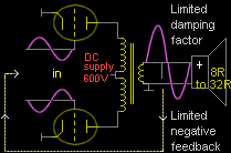
Damping factor Valve amps naturally function in quasi Current-drive having a high output Impedance with minimal damping. Negative feedback from the speaker terminals is fed back to the Cathode of the first input valve causes the Valve amplifier to shift slightly toward Voltage-drive reducing its output Impedance and introducing Damping factor to control the excessive Q Resonance of the speaker. Valve amps are naturally noisy (hum) and negative feedback quietness the amplifier and reduces measured distortion.
Negative feedback Academic engineers became obsessed with finding ways to increase negative feedback in Valve amplifiers to achieve a greater damping factor and lowest distortion figurers. But Valve amplifiers will only tolerate a minimum amount of negative feedback before the amp is caused to oscillate, hereby restricting the amount of Damping factor that can be achieved. When solid state amplifiers arrived with the ability to have 100% Damping factor, interest in Valve technology was discarded without further thought.
Pre 1970s many if not most large manufacturing companies maintained a strong class demarcation of management and engineers against trades and production workers. This demarcation was also reflected in music. Management and academic class was identified with Classical and Popular conservative music similar to Frank Sinatra or Julie Andrews "The sound of music" etc mostly mid range with minimal bass energy. The working class identified with music of the devil, Sex drugs Rock'n Roll, drums bass guitar, Jazz, Blues with intense bass energy.
The rock recording industry noticed that the new solid state amps caused most speakers to sound flat and lifeless. Without any standards in place, recordings had and have extensive EQ applied to boost the bass and hi-frequencies to compensate. Many guitar and bass amplifier designers also noticed that the new solid state amplifiers (with 100% Damping factor) had a suppressive effect on the musicality of a speakers performance and stayed with Valve technology. But academic engineers of HiFi amps were blindly obsessed with the almost perfect zero distortion figurers and 100% damping factor solid state amps could achieve. The concept of introducing variable current drive to manage speaker Damping was negated.
Thiel Small parameters www.wikipedia.org / Thiel Small Thiel Small parameters for speaker design were developed in the early 1970s, but little interest was taken untill computers were available in the 1980s. Each parameter of a speaker is compiled into a singular complex algorithm that enables a speakers performance to be accurately defined. The parameters assume the speaker is being driven with zero output Impedance (100% Damping factor) and will also optimise the performance of a speaker in a ported cabinet. Thiel Small parameters provided a new way to manage speaker design and re-obtain the lost bass energy caused by solid state amps in Voltage-drive, but mostly at the cost of reduced efficiency.

High power solid state amps were becoming available at low cost and the latest chemical engineering of epoxy compounds enabled speakers to be designed that were capable of 100s of Watts. With the applied use of Thiel Small design parameters it was seen that by increasing the mass of the cone, and decreasing the flux density BL by increasing the gap tolerance, coupled with a stiff suspension to enable speaker manufacturers to assemble speakers with wider tolerances enabling lower cost mechanised production the end result is a speaker that is less efficient compared to previous times, but with cheap high power amps the result can be accurately calculated to give the low frequency performance required.
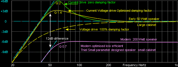
The below pic shows a generalised graph of an early design 50 Watt high efficient speaker (yellow) with a low mass cone and soft compliance in a typical large sealed cabinet. With zero damping the resonance Q2 the speaker is extreme +6dB. With a set amount of damping provided by the Valve amplifiers negative feedback the resonant Q1.4 is reduced to +3dB at 60Hz, and is flat again at 40Hz and only down -3dB at 34Hz. The music will sound deep and warm with extra responsive bass energy.

When the same high efficient speaker (yellow dash) is driven by a solid state amp (100% Damping factor) the speakers resonance is completely damped and the bass response begins to roll off from above 100Hz. Bass energy at 50Hz reduced -6dB. The music will sound flat and shallow.
With a modern less efficient 200 Watt Thiel Small designed speaker with a heavy cone placed in a small sealed cabinet driven by a solid state amp (100% Damping factor) the response is almost flat down to 60Hz and reduced -6dB at 40Hz. The modern speaker has an academically flatter response and the music sounds as we hear it to be.

By comparison many earlier speakers in larger cabinets were 6dB to 12dB more efficient than most modern speaker systems today. Many modern speakers now have to be driven with x 4 power to sound as loud. High powered solid state amplifiers are now cheap and wasting power is symbolic of modern times. History has been forgotten and there is little interest in reflecting on what was not understood during the transition from valve to solid state technology.
All that was required was a simple addition to the gain management of solid state amps (in the right pic) to enable Voltage to Current drive adjustment so the Damping factor of speakers could be effectively managed.
The historical purpose of organised religions was to manage society to un-questioning obey authority and live within a moral code. Over thousands of years religious conditioning has become so entrenched within human consciousness that it no longer requires us to worship Deity's or repeat ancient text as a guide for obedience. Marketing and consumerism is the religion of modern times.
Modern man is so conditioned by his past, that he will blindly accept anything marketed to him, including identifying with brand names, model numbers and celebrities. He also infallibility believes in the propagandaised ideal of Democratic consumerism as a disguise for self-interest. Above all, western man remains a contradiction to himself as he will always choose to be right, rather than choose to be happy.
Voltage drive may not always give a pleasing sound but it provides superior technical measured performance of zero output Impedance (100% damping factor) and the primary reason it was un-questionably chosen, reflecting one of many examples from our historical religious conditioning now expressed as a self-righteous belief in an imposed technical morality.
sound.whsites.net is a parallel site by Rod Elliott that has a detailed description of amplifier design, and is essential reading for those who require an advanced mathematical and electronic design explanation of the amplifier principles described on this page.


